Craig Moore - Electronic Objects Blog

Professor - Rob Duarte - Spring 2023
Lab 4 - Analog Inputs on UNO R3 - January 26, 2023
Covering the basics of using analog inputs with the Uno R3
Prep
- I started this lab by familiarizing myself with some vocabulary. The Sparkfun website has a great tutorial outlining the difference between Serial and Parallel interfaces- the latter sends bits of data sequentially, one after the other, while the former uses an array of wires to transport. I found the following schematic very helpful in visualizing this process.

- With a deeper understanding of the vocabulary, I read over the entire lab doccument again before getting to work on the first excercise.
Process
1: Serial Output
- I copied the code from the lab doccument, built it and uploaded it without any problems.
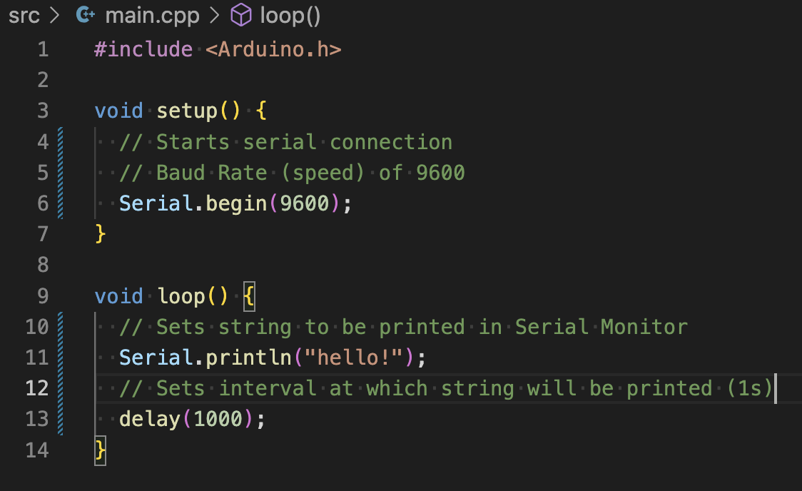
- The Serial Monitor printed “hello!” once per second.
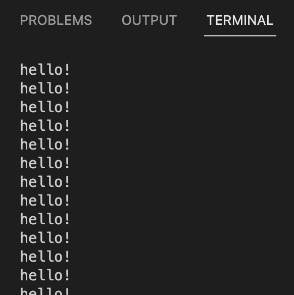
- Taking the time to study each of the functions in the code, I took note of a new term/unit: Baud Rate: Unit of measurement for symbol rate, in this case, 9600 bits per second. I still have more questions about this, but for the sake of the lab, an intuitive understanding will do.
2: Voltage Divider
-
To assist with the process of rebuilding a voltage divider, I was able to refer back to my previous blog post for guidance, imagine that!
-
I opted to build the voltage divider using two 1k ohm resistors.
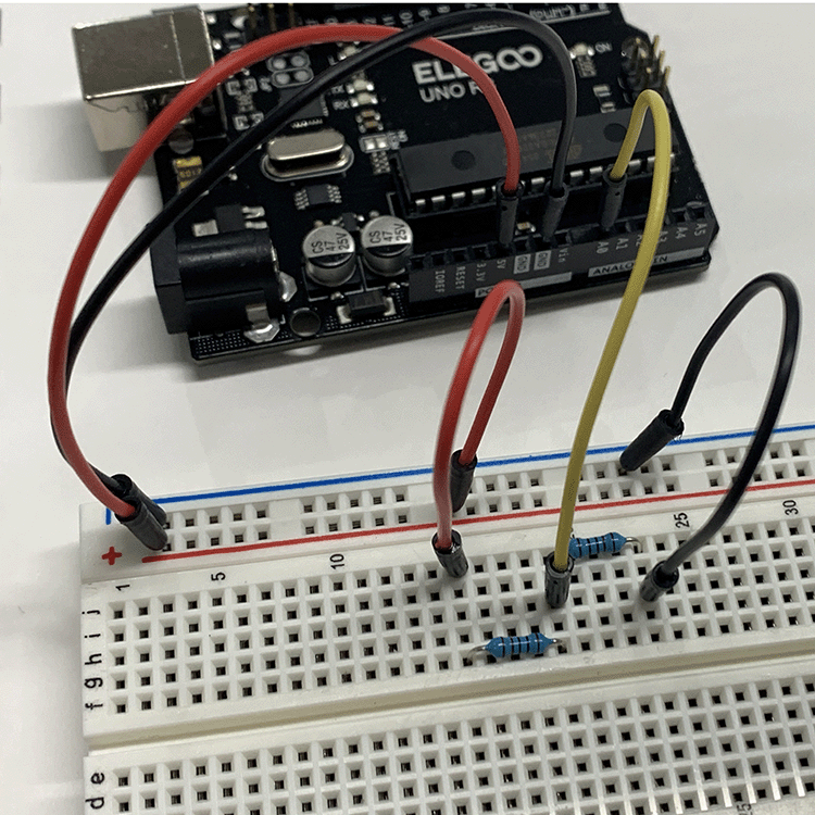
- With the breadboard built out, I copied the code, taking the time to add my own notes in an effort to understand what it’s doing.
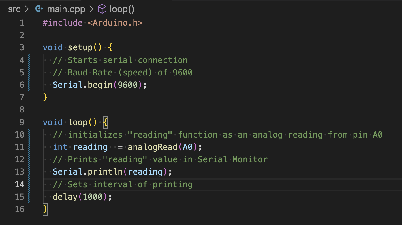
- After building and uploading, I had what looked like success, although I couldn’t be sure until I converted the analog reading to volts.
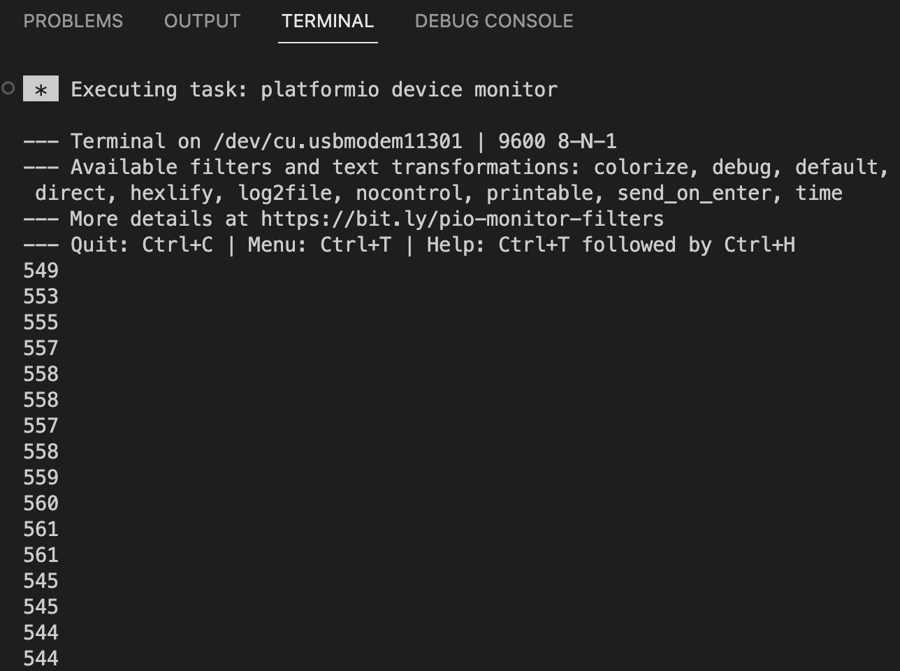
2.5: Showing Volts Instead
- I copied the new “float” line of code and moved it around until I found the right place for it, which was after “reading” was initialized, but before the Serial Monitor is told to print “voltage”
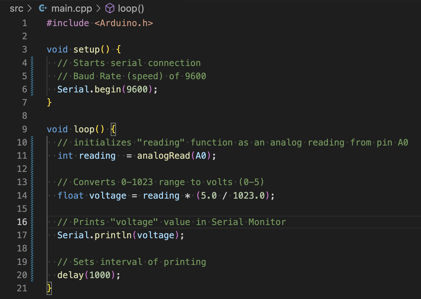
- With the new conversion code installed, I uploaded it to the controller and had success.
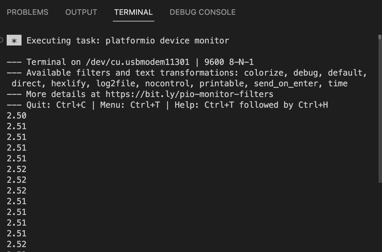
- Finally, I copied the print code to display both “reading” and “voltage” in the Serial Monitor
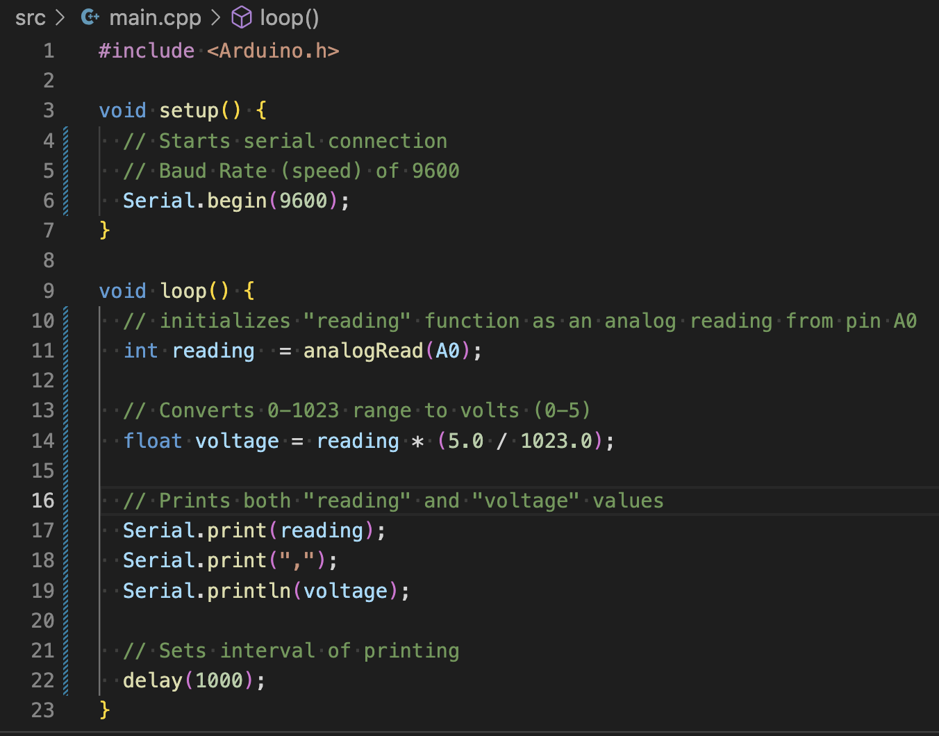
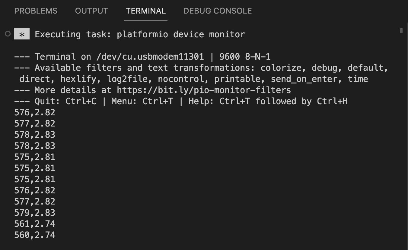
- From what I can gather, println is used to finalize a list of print requests. I think it means “print line”
3: Potentiometer
- I started by modifing my breadboard to use a potentiometer instead of resistors
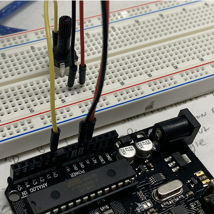
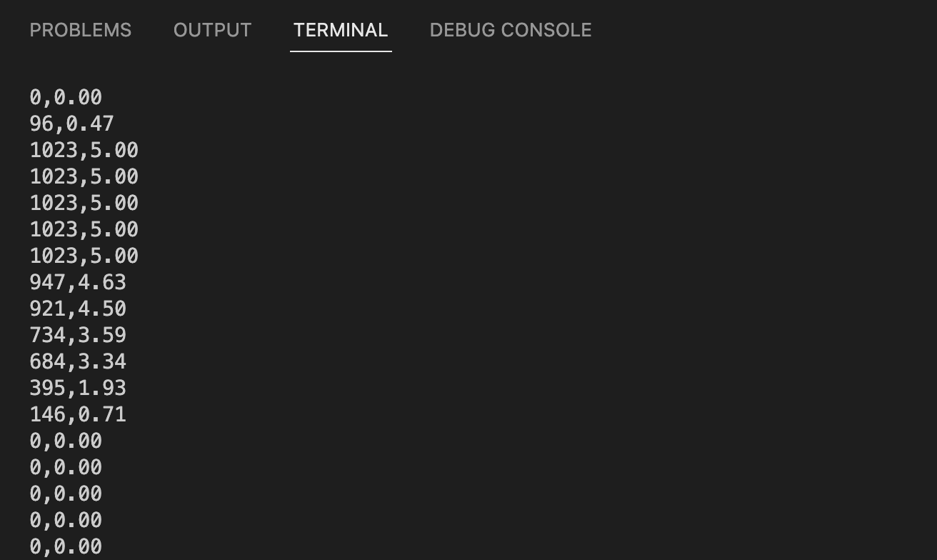
- Uploading the same code as in Excersise 2.5, the Potentiometer Voltage Divider worked on first try. It was turned all the way down to start. I turned it all the way up, then gradually reduced it to zero as seen in the Serial Monitor
4: Controlling the Brightness of an LED
- The lab doc suggested leaving the previous circut in place, but I decided to make some modifications for the sake of usability.
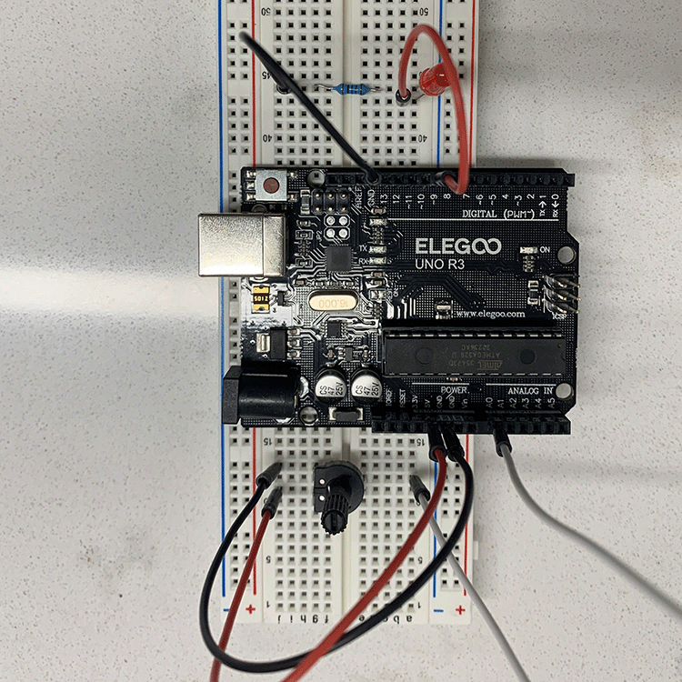
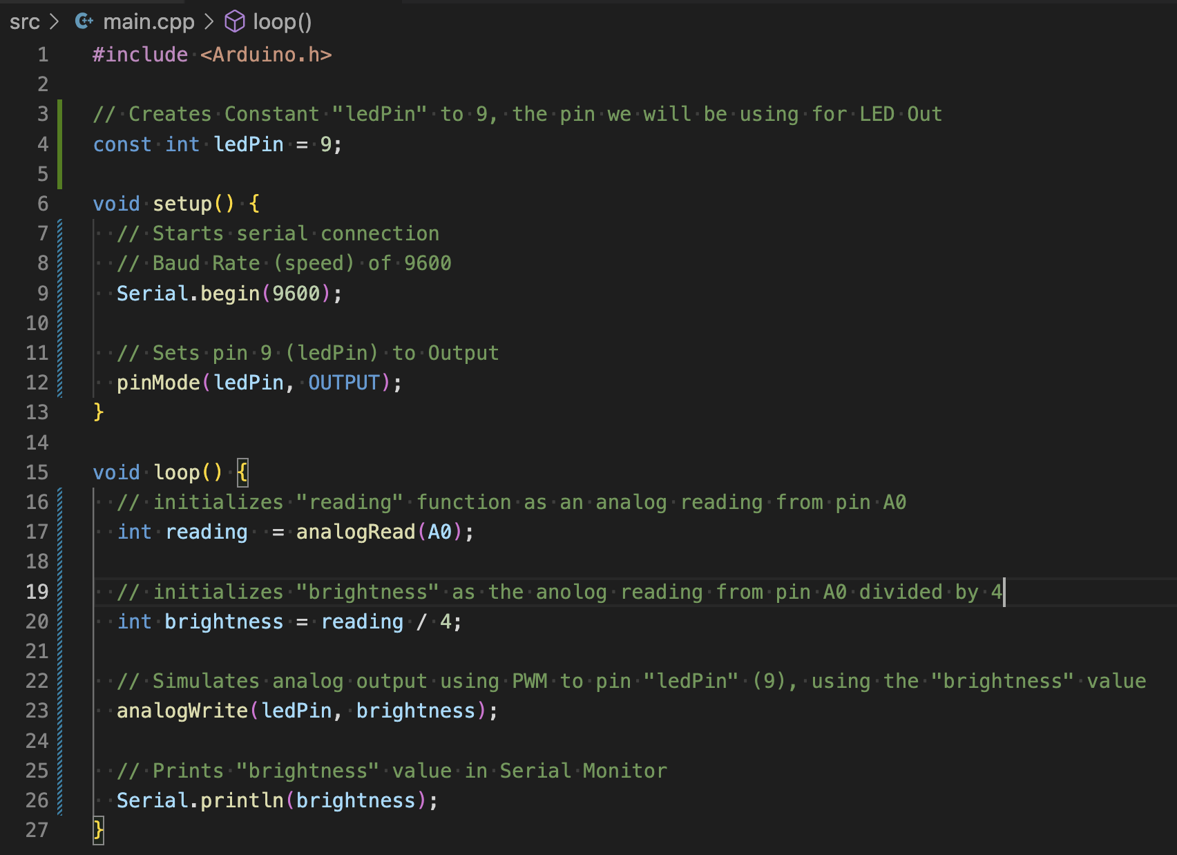
- I copied over the new bit of code, noting how the analogWrite function uses Pulse Width Modulation to simulate an analog signal to dim the LED
-
I think that we divide reading by 4 to give the LED a signal output that wont overload it. We know from the first excercise that the signal from A0 provides values ranging from 0-1023, which would be too much for the LED.
-
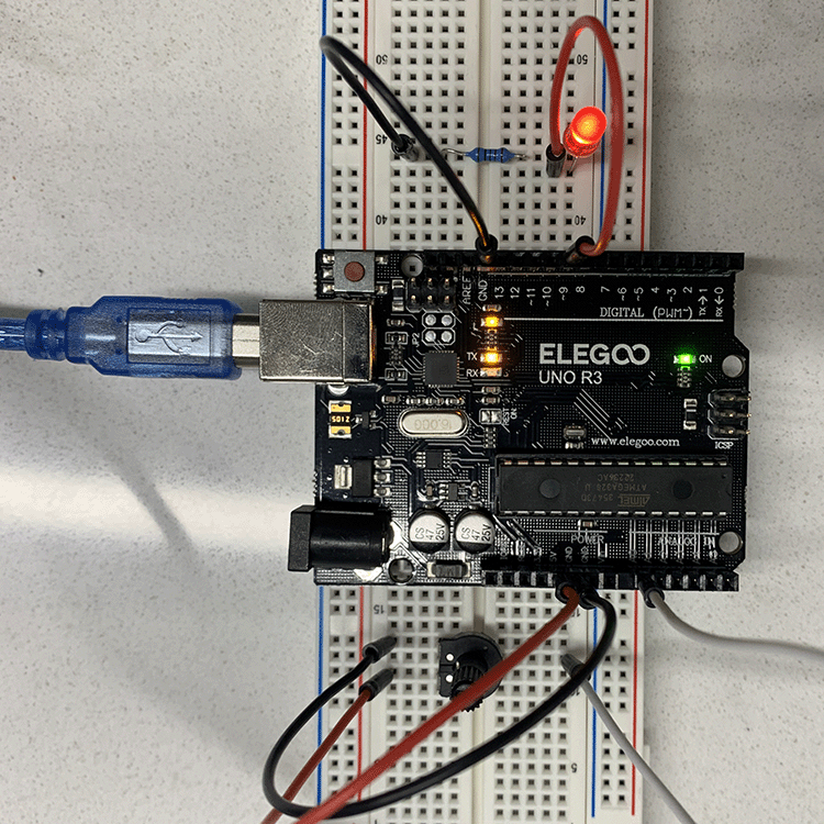
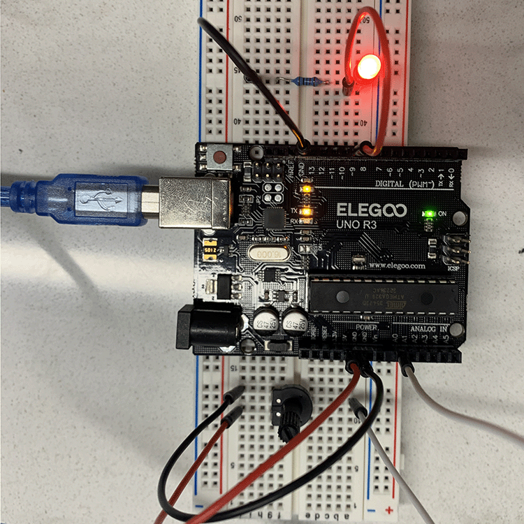
Having created the code and built the breadboard, I tested it out. I had success, but the potentiometer that comes with the kit is terrible. I had to hold the base in place to get a consistent signal that didnt flicker.
-
With that said, my circut did work and I was able to adjust the brightness of the LED using PWM. At lower values, it was more obvious that I was using a modulated pulse to control the brightness.
5: Light Sensor
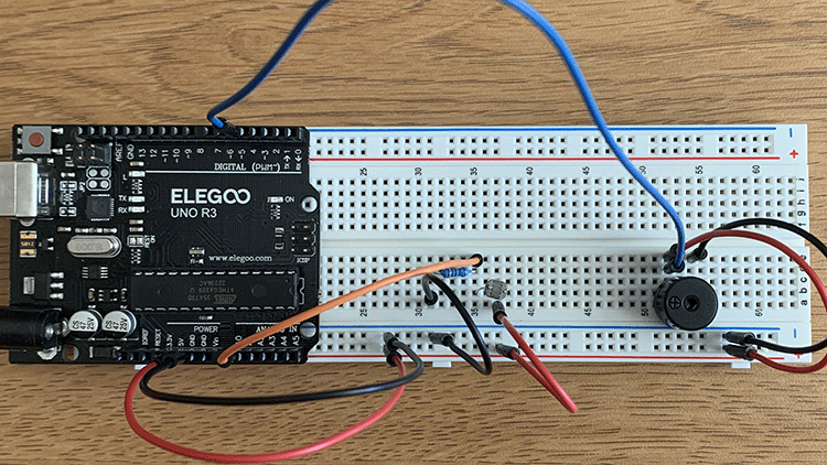
- I built the breadboard based on the schematic in the lab doc, and wrote the code, which was very similar to the first excercise.
-
Looking at the Serial Monitor, I noticed that the ambient light in my room was producing a value around 375. When I cover it with my finger, I get it down to about 120. Shining a flashlight at it produces around 750.
-
Starting with my min/max values set at 120, 375, I uploaded the new code and got the buzzer working and repsonding to changes in light.
-
After a tinkering with the values, I found a min/max that worked with my room and created the widest diversity of tones on the buzzer.
-
I took a video as documentation of success but will omit that from the blog
Conclusion
-
At the end of this lab, I am left with a greater understanding of the basic capabilities of a microcontroller and am beginning to grasp how basic data (output voltage, ambient light) can be scaled up or down to control almost anything.
-
With that said, I still have some remaining questions about the differences between synchronous/asynchronous comunication.
-
Also, I am having a hard time grasping exactly which unit of measurement the controller is using when outputting the unconverted analog signal.
-
Moreover, I need some more elaboration on what baud rate controls and how to know when to alter the 9600 value
-
This lab took about 4.5 hours from beginning to end. I experimented with updating the blog directly as I completed the lab, which I think I will continue to do in the future.